A look at the installation of our own Camos Crank-up satellite dish

May 2009
Last edited: 21/7/09

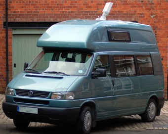
In May 2009 we succumbed to the attraction of not having to unpack / stow our portable dish and other paraphernalia. Do it quick and do it inside, without going out into the rain: this sounded good. And the Camos Crank-up manual dish is so compact and lightweight that it could be fitted on even our crowded high-top roof.
It is also very reasonably priced while being a very well designed and well built product.
Here is a brief description of our experience: what you get, what’s involved in the install; and how well does it work?
Take a look at the PHOTO GALLERY where you can view pictures singly or as a large screen slide show.
Installation process
Why we opted for the crank-up
How time flies: at the time of writing it’s already two months since our crank-up was installed and I’m feeling a little vague about the details but on the other hand this is a good sign that everything was relatively straight forward.
What was in the box
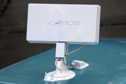
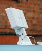
The easiest way to get a clear idea of the crank-up’s parts is to view the photo gallery which illustrates them all. But broadly it consists of the exterior main assembly which is a neat alloy casting which contains the rising / falling mechanism which allows the dish to be elevated and parked. The plate at the bottom of the assembly is fixed to the roof (explained in more detail later) and the upper part of the assembly rotates smoothly so that the dish can be pointed at the satellite direction.
The dish itself is a rectangular planar type: inside the casing there is an array of multiple signal receivers, unlike a parabolic dish which collects the signals falling upon it and focusses them onto a single receiver. The dishing mounting arms slot and bolt to the crank-ups main assembly so that it elevates and rotates with the mechanism.
This exterior parts are connected to the interior via a splined rotation shaft and a smaller diameter five-sided elevation shaft which is passed through a hole in the roof. Inside, two parts fit over the spindle. One is a large plastic handwheel with a long plastic shaft which is splined on the inside and fits over and engages with the broader splined alloy shaft which protrudes into the hole from the roof mechanism; turning the handwheel rotates the dish. The other is the crank handle which attached to the smaller shaft: when the handle is turned it drives gearing in the roof mechanism which raises or lowers the dish elevation.
In fact the handwheel is in two parts: the large handgrip with its pointer and splined shaft is separate from a base plate which is fixed to the ceiling and cannot rotate but the two parts engage via a large diameter toothed ring. Normally the two parts act as one because the toothed rings are kept engaged by a spring and this means that the dish rotation is locked and cannot be moved by wind or other external influences. When setting up the dish, the handwheel is pulled down slightly against the spring pressure to disengage the teeth so that the wheel - and the dish with it - can be rotated until the pointer is aligned with the desired satellite position on the graduation dial.
The remaining parts supplied are the coaxial satllite cable (5 metres) with connectors, and a waterproof cable entry box. Mounting screws are also supplied, and a template to help you to choose the position on your roof. You will need to obtain a tube of Sikaflex adhesive / sealant as this is not included.
Installing the parts - an overview in one sentence!
Having described the parts at some length I don’t want to give the impression that installing it all is a complicated process - so here it is in a nutshell:
Decide on the exact position on the roof and drill a hole for the shaft then fix down the main assembly (with dish attached) over the hole before attaching the handwheel and crank handle to the shaft inside the wheel; finally, drill the hole for the cable and fit the waterproof box and cable which is then attached to the dish and to the satellite receiver inside the motorhome.
OK, not so fast - a little more detail
I’ll now err on the other side and go into tedious detail which might tend to make the whole process seem overly involved but then so would a description of getting out of bed in the morning if you had to document every step ...
I will describe what was entailed in our own installation in each of these steps. Some of the considerations will be simpler and easier in a different motorhome but it is unlikely that anything will be much harder. The amount of work also depends on how meticulous you want to be about neatness and thorough preparation.
Before beginning, loosely mount the dish box to the main assembly so that it is in the parked position then measure the total distance front to back and make a note of this figure, as well the width of the dish. This is because the paper template supplied is only of the base for the main mechanism and the instructions do not provide the dimension including the parked dish.
Where
Now you are ready to decide on the position on the roof - use the paper template to gauge where the base of the main mechanism and the shaft hole should be located, taking into account the attached dish and other objects on the roof, strength and levelness and smoothness of the roof and whether the hole will pass through the roof at a suitable place without damaging anything within the structure of the roof or on the ceiling underneath. Consider also that the hole inside must emerge at a point where there is room for the graduation disc and the larger ceiling plate and room to be able to reach it and operate it easily. Also bear in mind the ease of routing the cable to the the place inside where your satellite receiver will be located.
In many ways this is the most time consuming part of the installation because you want to think carefully before drilling your hole.
Get going
In our case there was really only one suitable place and this met all requirements except that it was not the strongest area of the roof because there was no reinforcing here between the outer and inner GRP skins which means that the roof might flex rather more than seemed desirable. The crank-up’s very low weight - only 5.5kg - was reassuring but nevertheless we decided to take an extra precaution: after drilling the 38cm hole through both skins we injected a rapid setting expanding foam which nicely filled the cavity for an area around the hole, at the same time bonding to the two skins to form an area of foam ‘sandwich’. Note that the foam was a two part variety which mixed automatically in the nozzle of its cartridge and did not require any moisture to be present, unlike some cartridge or aerosol foam products used for wall gap filling. Our foam sets in about a minute and you can’t stop once you begin because the foam will solidify in the cartridge nozzle. Cause for some tension in the operator - me - but it did the job.
A word of advice about drilling the hole when the roof is thick: take care to keep the hole as perpendicular to the inside and outside surface as possible so that both the outside base plate and the inside ceiling plate - which are parallel to each other - are also flat and parallel with the roof and ceiling surfaces.
If you are working outdoors it’s a good idea to have available a roll of duck tape - which will effectively waterproof the hole if you have to abandon proceedings temporarily due to rain.
Ready to fit
Fitting the main mechanism was fairly straightforward. We used masking tape to lightly tape the paper template in position, then more masking tape to apply a border all around the template, following its shape; this was to protect the adjacent roof area from extruded Sikaflex. Once masked off, we removed the template and prepared the roof surface so that the Sikaflex (which is the main fastening for the unit, in my view) would bond as strongly as possible. We used a fine nylon Scotch abrasive cleaning pad to lightly abrade the surface and afterwards degreased it; for this we wiped it with a brake-cleaning solvent but white spirit is also suitable. The same treatment was applied to the underside of the base. Wipe dry as well.
Before this final clean we replaced the base within the masked-off area and drilled small pilot holes through the base plate holes for the ring of small fixing screws.
Finally we were ready to apply the Sikaflex (a bead 5mm diameter all round the base edges, screw holes and other vulnerable points). The base was then placed in position and the screws tightened down carefully so that the Sikalex was extruded all around the base. Note that the screws should not be used to tighten down so much that the base is pulled hard against the roof surface, thereby squeezing out all the Sikaflex. Sika suggests that the final thickness of this layer should be about 2mm. When it has set it provides a very stong, cushioned bond and is completely waterproof. Smooth the Sikaflex neatly where it has extruded from under the base using something suitable (OK, a finger tip but be careful what you touch because it is easy to spread it everywhere; also tiresome to remove so wash you hands as soon as you have finished). Then immediately remove the masking tape before the Sikaflex starts to set.
Cable through the roof
The final job topside is the fitting of the cable. The instructions advise that the cable box should be located 10-13cm in front of the base; at this distance the recommended amount of cable between the dish and the box will allow sufficient freedom for the dish to swivel. Camos even supply the cable with a rubber marker sleeve fixed at the recommended cablle length.
Note when connecting the cable to the dish that the route should be through both of the grommeted holes in the side plate. The illustration in the instructions is not clear and initially I used only one hole, with the cable then passing out at top centre, as can be seen in the photographs in the slide show. This is wrong because the cable can get pinched if the dish is raised fully. When I realised this I re-routed the cable.
One end of the cable is pre-fitted with the connector which is attached to the dish. Tighten the connector firmly but do not overdo it. Ensure that you then fit the special waterproof cap around the connector; it is vital that water is not allowed to enter the connector and the dish. The plastic cab is hinged along one long side and clips together on the other side; open and you will find that it is filled with a peculiar gel. Close it again over the connector, keeping it as close as possible against the dish body and make sure that the clips engage again. This is a bit fiddly because the plastic is black and it is quite hard to see whether the clips are properly located; but then I can’t see a lot of things properly these days.
The end cap of the main cable entry box, and the box itself, is then passed onto the other end of the cable and the cable is fed through a 13cm hole positioned in the roof in front of the unit, as described earlier. The area of roof around the hole, and the underside of the box, should be degreased first. Again, we taped around the box first to keep the Sikaflex from spreading. Apply a bead of Sikaflex and press the box down lightly over the hole, ensuring that it extrudes all round but again leaving a layer around 2mm thick. Smooth the edge and remove the masking tape.
To stop the cable from tilting or lifting the box before the adhesive has set lightly weight it down or tape it down.
And so to the inside
The plastic shaft of the handwheel now has to be cut to length (easy with a hacksaw); the length is determined by the roof thickness. There is no guidance in the instructions on how to decide this length but in fact it’s quite simple. First fix the large celling back plate in place (or two two can be used, according to roof thickness; which is explained in the instructions).
Now locate the handwheel assembly in the hole so that it meshes with the splined shaft of the main unit and insert it as far as it will go: the base of the handwheel and tooth ring has to end up flat against the ceiling plate but its plastic shaft will be too long at this stage so there will be a gap. Measure this gap and that’s the amount that you have to cut off (plus say an extra couple of millimeters to give some clearance).
You can now put the graduated disc in place and fix the handwheel and ring gear using the small screws (or were they bolts?) provided.
The smaller diameter metal shaft which extends down through the roof now has to be cut to length. To determine the length place the crank handle on the metal shaft - ensuring that it is fully home in the socket in the crank handle - and measure the gap between the top of the crank handle and the bottom of the handwheel; the amount of shaft you need to cut off is around 5mm less than this gap. Do not cut off the same amount as the gap because then when you fix the crank handle on to the shaft the handle will be right up against the handwheel but this is wrong - there must be a gap so that the handwheel can be moved down against its spring loading in order to release the toothed ring and allow the dish to be rotated. When you are sure about the amount to cut off this is easily done with a hacksaw: the shaft is made of alloy and cuts very easily.
Getting cable to receiver
That completes all the work which is directly a part of the dish installation but there is one remaining job which is quite simple, or a pain, depending on how easy it is to run the cable from the entry point inside to the location of your satellite receiver. In our case, the double skin roof in theory made a handy path through which to run the cable to the cupboard which houses the receiver; in practice it was very difficult to fish it through because the void is filled with fiberglass insulation and other obstructions and we had to steer and navigate blind to a small exit hole in the cupboard.
I could have been less fussy about hiding the cable completely and this would have been much simpler. With hindsight, an even simpler way would have been to route and secure the cable along the outside of the roof to a point where the hole could have been drilled directly above the receiver location and the cable dropped straight through to its final destination. On the other hand, inside means the cable is safer.
The Camos Crank-up in use - how does it fare? Exceedingly well.
We have now been able to test the dish more extensively in use for real and the simple conclusion is - delighted.
There is no longer any debate about whether or not it’s worth putting out the dish because we are only only ‘here’ for one night. It is so quick and effortless that it goes up every time; we might only watch the news but it was no bother to do it.
And in the morning, whether we are moving on from the site or just heading out for the day, it is literally a matter of 15 seconds to park the crank-up in its travelling position.
It is so easy that we have even watched the news during a lunch stop in an otherwise very dull lay-by; mmm, partly I was showing off to my wife, I’d have to admit.
Set-up tips?
So, any tips about getting the dish aligned with the satellite? I have to say that I’ve got better and faster after some experimenting. With any type of manual dish you need to know the elevation angle and the direction of the satellite that you want to receive the signal from. This will vary in different locations and the larger booklet that is supplied with the crank-up includes tables for the settings at various locations in the UK and other European countries.
It is easiest to start with the elevation needed for the satellite; then you turn the crank handle the required number of turns (following the guide on the disc).
The unit even comes with basic compass to help you find North; you then set the dial’s North mark to this direction and then rotate the dish until the direction pointer is within an arc which is marked on the disc for each satellite. If you turn through the arc without success adjust the elevation up or down by around a quarter turn and try again. Once you locate the satellite you can fine tune the signal strength with small adjustments, if needed.
Aligning the dish can be easier if you use a sat finder which is connected between the end of the cable and the receiver; the finders have an audible tone so it is not necessary to be able to see it if the receiver is in a cupboard. I have fitted one and leave it in position, with the sensitivity control turned right down so that there is no reaction from it; so far I have not found that it attenuates the signal.
Remember that the compass reading will be distorted by the vehicle body so it is best to take a reading from outside and then note a landmark which corresponds to North and then turn your North mark on the dial towards this; although this can be difficult to judge. The fastest way can be to use a compass with a rotating bezel (they are cheap to buy) which can be set to the satellite bearing (from the tables); you then turn the compass until its needle points to north and the compass’s pointer is then aiming directly at the satellite. Again, you should do this outside and again note a landmark; its quite easy to aim the dish towards this landmark from inside.
A couple of refinements in technique: if the vehicle is parked on a pronounced slope take this into account when setting the initial elevation: if the roof, looking towards the direction of the satellite, is already pointing upwards (or downwards) then the angle you crank up the dish is increased (or reduced) accordingly.
Once again, the telling of all this detail might make the process seem complicated but really it is not. It is claimed that it takes generally under a minute and I reckon that’s about right. I have even hit a bull’s eye without having switched on the receiver first: demonstrating to a friend, I explained that I would crank up an initial 9 turns (done) then rotate to about ‘there’, because I knew that the satellite was in that general direction (done).
Then I would turn on the receiver (done) and narrow it down and - Oh my goodness, the picture is there already! Sheer luck. Well, he was impressed but not as impressed as he would have been if he had been familiar with the alternative of unpacking, deploying and aligning a portable dish (often in the rain) ....
And one last tip: I have a bright fluorescent orange quick-clip that I attach to the crank handle after I have parked the dish. Before I can use it again I have to take the clip off and then I clip it over the top of the steering wheel to store it. Even I can’t drive off with a big orange clip starting me in the face and my crank-up still .... cranked up.
© All content copyright of Enetgy Limited - enetgy.co.uk - for campervanstuff.com, 2009
